Improving Measurement Accuracy for High Frequency RF Connectors
Download PDFAbstract
Improving the accuracy of your microwave test and measurement equipment becomes increasingly important when high frequency devices are used in the transmission paths of radio, cellular, satellite and digital communications. This discussion helps to solve problems with measurement errors during and after calibration of your microwave test instrument.
Introduction
The wireless communication industry is a giant compared to the early 1980s when analog cellular was all the rage. The advent of digital communications and cellular phones, as well as the infrastructure around it, from mountain top base stations to satellite links, has driven designers to create RF connector products that will meet the demands of increasing electrical performance specifications. RF Precision Products employs engineers with diverse backgrounds in RF connector design. Their design and manufacturing knowledge base includes precision connectors and adapters, coaxial cable assemblies, medical cable assemblies and wireless digital spread spectrum modems. With the latest in design software at their disposal, they ensure that all products meet or exceed customer expectations. These high frequency products need to be verified to performance parameters specified by the design engineer or to customers’ specifications. The need for test and measurement equipment that ensure products meet or exceed these expectations is a necessary expense. A Network Analyzer is a microwave test set that is used to characterize an RF device. Network analyzers will transmit a signal or a band of signals through active or passive devices and then project the complex impedance, magnitude and phase onto the analyzer’s on-board display.
Some network analyzers have measurement ranges that exceed 100 GHz. The need for measurement accuracy becomes more critical at frequencies above 1 GHz. The test set up and calibration is the most important factors for error corrected measurements when frequencies increase exponentially. Network analyzers were primarily designed to measure insertable devices where one port would have a plug (male) connector and the other port would have a jack (female). During the through1 transmission step in the calibration procedure, the two ports are connected via test port cables. Challenges exist when testing adapters or cable assemblies with connector ends that do not attach directly to the test ports on the network analyzer.
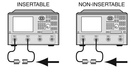
What is a non-insertable device?
A non-insertable device is a product with interconnecting ends that differ from the analyzer’s test port connectors.(Fig.1) They may have the same gender or they may have connectors with differing families, also known as “between-series”. In each case, the device under test (DUT) you are attempting to connect to your network analyzer will introduce errors in the measurement plane due to the inability to remove these errors during calibration. With the proliferation of the latest in network analyzer technology, enhanced calibration methods for measuring non-insertable devices were introduced and integrated into the analyzer’s software/firmware. Most analyzers today have detailed instructions built into the calibration menus that describe the set up and calibration steps necessary to include error correction for these types of devices. The menus also include instructions for fixed mechanical calibration standards and electronic (Ecal) modules.
Which calibration method should you choose for enhanced calibration?
Zero Length Thru Method
The most proficient and fastest method is called the “Zero-Length Thru” method. If testing for an insertable device, the test ports are calibrated individually and then connected directly together during the thru sequence. No delay, loss, capacitance or inductance compensation was required during this process. The calibration plane is now at the test port connector’s electrical reference plane. The device (DUT) is inserted between the test ports. The device’s response is now displayed on a graphical overlay showing the measurement result in Logarithmic or Linear format. Other formats can be added to the display and shown simultaneously depending on the network analyzer model you have.
Adapter Removal Method2
This method produces a very accurate measurement, however it is labor intensive and requires connecting and disconnecting adapters from the test port cables, which introduce measurement errors into the calibration plane should any of them become loose. You must save calibration states for each adapter on each port into the analyzers memory. You “recall” the states after the calibration steps are complete and the data is joined together using a complex algorithm generated by the analyzer’s software.
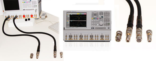
Swap Equal Adapters Method
This is the preferred method for RF Precision Products’ technical staff. It is by far the easiest to do and is also very accurate. It requires you to set up as if you were measuring for a non-insertable device, calibrate both ports using your open short and load standards (or Ecal) and then remove one of the port adapters to attach a high quality phase equal adapter for the thru portion of the calibration procedure. The traditional method is to use a thru adapter that matches the DUT’s exact phase and delay characteristics. An adapter of this type is not always available when you need it and in most cases is required to be a custom built item. In order for this adapter to be included in the cal set, it would require you to edit a stored calibration set. The adapter’s delay and other characteristics would need to be known before re-writing the cal set. A better method is to have test port cables that allow you to change the test port connectors.(fig. 2) After calibrating both ports, you remove the calibrated adapter from one of the test port cables and then attach a high quality phase-equal adapter in its place in order to do the thru sequence. After the thru portion of the calibration procedure is complete, the original calibrated port adapter can be re-installed. The loss and reflection from the un-calibrated phase-equal adapter (used as the thru) is negligible and adds almost no error into the measurement. You can purchase phase-equal adapters and test port cables from RF Precision Products or other companies that specialize in producing test and measurement accessories.
Between-Series Method
This example presents the most challenging of all methods when calibrating for a repeatable error corrected measurement. The connectors are usually comprised of one type on one end and a completely different type on the other. With no practical means to calibrate this type of device, you are left to decide which calibration kit to use as the reference standard for one end while ignoring the other. RF Precision Products uses Agilent PNAs as the network analyzer of choice. Our PNAs have enhanced menus that ease the calibration process when high frequency connectors or other devices require you see the real time responses up to 40 GHz and beyond. You can effectively correct for non-insertable or between series devices if you follow the set up and calibration steps carefully. A couple of features to highlight are the IF Bandwidth (IFBW), additional Time Domain and Automatic Port Extension settings. The IFBW on these models can be adjusted down to 10 Hz or below, allowing you to lower the noise floor significantly. The time domain menu allows for setting physical length based on the devices’ velocity and displaying the one-way response vs. the traditional two-way response. The units of length can be selected to display millimeter, inch or feet. Another feature is the automatic port extension (APE) function. This allows you to add an adapter or cable jumper onto one or both of the calibrated ports. Applying APE after the initial calibration will automatically compensate for the added length by an extrapolation of a best curved-fit algorithm. The loss, delay and other characteristics locate to a new calibration reference plane. Using a short or open is all that is required for this feature to correct the intrinsic errors in the added port extension(s).
Conclusion
Having the ability to design and manufacture high frequency RF connector products that meet strict electrical requirements is what our customers have come to rely on. The incorporation of the right microwave test equipment and accessories are mandatory for connector manufacturers who want to stand out and be leaders in the ever changing wireless communications industry. You’ll have confidence in your measurement data applying these enhanced calibration techniques and, if performed correctly, will assure repeatable error corrected measurements each time.
References:
- 1 Commonly known as the "thru" sequence of the calibration set up
- 2 Agilent Application Notes 1291-1B and 1287-3, www.agilent.com
Copyright ©2024 RF Industries