Optimize Your RF/MW Coaxial Connections
Download PDFRF/microwave connectors are small and often overlooked, but they serve as gateways for many electronic devices and systems, linking components and systems together to enable proper operation. Coaxial connectors are often taken for granted—until they fail. They are instrumental to the operation of many electronic devices and systems, from cellular telephones and wireless data networks to the most advanced radar and electronic-warfare (EW) systems. Whether designing or simply maintaining electronic devices and systems, understanding the role of the RF/microwave connector can help to boost both performance and reliability.
Before exploring technical details about connectors, it might help to review some of their history. Connectors come in many shapes and sizes. They are used in a variety of electronic devices, from audio through millimeter-wave frequencies. The interface dimensions, machine tolerances, materials, even the plating and finish on those materials, all contribute to how well and how reliably a connector performs. Coaxial connectors are designed for mounting on the end of coaxial cables, on printed-circuit boards (PCBs), on panels, and on many different electronic component and device packages. Why there are so many different types of coaxial connectors and adapters is largely a matter of RF/microwave history and the evolution of high-frequency technology. With the evolving demands of higher-frequency applications, connector developers are pushed to achieve ever higher frequencies, smaller footprints, unique interfaces, and better performance with their designs.
Anyone who has assembled a cable-television (CATV) system, with its F-type connector/cable assemblies, will appreciate the convenience of an electrical connector without necessarily being aware of its electrical and mechanical benefits. First and foremost, the use of a coaxial connector saves time and effort. In the case of assembling components such as amplifiers and filters with coaxial connectors, joining two components by mating male (plug) and female (jack) connector pairs is simpler and faster than soldering or hard-wiring a connection between the two components. And most coupled connectors can be readily disengaged when needed, to simplify component maintenance within a system.
The number of coaxial connectors currently in use is largely a function of the expanded number of frequency bands in use at RF/microwave frequencies needed to satisfy growing demands for such applications as voice, video, and data communications. Small connector dimensions usually translate into higher operating frequencies. Currently, coaxial connector designs are available for frequency ranges as wide as DC through 125 GHz. RF/microwave coaxial connector configurations include straight and right-angle versions for use terminating coaxial cables, bulkhead and flange-mount connectors for use on equipment panels and component packages, end-launch, right-angle, or vertical PCB connectors, and even push-on connectors for hard-to-reach electrical connections. But prior to World War II, the UHF connector, with a frequency range of about DC to 300 MHz, was the only coaxial connector in use for RF components and systems.
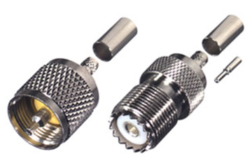
For many years, the UHF connector provided reliable service for applications through about 300 MHz. (FIG. 1) But with World War II, and emerging military needs for higher-frequency applications including communications and radar systems, the UHF connector—with its nonconstant impedance—was distinctly unsuitable for higher-frequency applications. A joint US Army-Navy RF Cable Coordinating Committee (ANRFCCC) was established in the early 1940s to develop electrical and mechanical standards for coaxial cables, connectors, and rigid high-frequency transmission lines for use with communications radios and radar systems. The committee’s goals and findings were later incorporated into the Armed Services Electro-Standards Agency (ASESA) and eventually wrapped into the Defense Electronics Supply Center (DESC), which continues present-day work on connector standardization for the US military.
The ANRFCCC introduced the Type N connector with its threaded coupling nut and air interface in 1942. The new connector was named after Paul Neill of Bell Laboratories, also a member of the ANRFCCC. A high-voltage version of the Type N connector, the HN connector, was later released and then the Type C connector with a twist-lock coupling mechanism for rapid connection and disconnection. It was named after its inventor, Carl Concelman of Amphenol Corporation. Smaller coaxial connectors would follow including the bayonet-type BNC and threaded TNC connectors developed by Neill and Concelman.
Type N connectors were originally covered in specifications written by the US Navy Bureau of Ships, which eventually became military specification MIL-C-71 until MIL-C-39012, was issued in 1964 to control the specifications for the Type N connector for military applications. Early Type N connectors had many shortcomings, prompting industrial suppliers to modify dimensions in their attempts to improve performance. A number of interface variations were developed, particularly by test and measurement companies for instrumentation applications, enabling Type N performance through about 18 GHz. But general-purpose Type N connectors, which perform to about 11 GHz, are covered under MIL-C-39012 for military applications.
At present, one of the more popular coaxial RF/microwave connectors is the subminiature Type A or SMA connector. It began life as the Bendix real miniature (BRM) connector, designed by James Cheal of Bendix Research Laboratories in 1958 and eventually becoming the SMA connector as a result of work by Omni-Spectra (now M/A-COM Technology Solutions) to convert it into their Omni Spectra miniature (or OSM) connector. The SMA connector was originally intended for use with 0.141-in.-diameter semirigid coaxial cable, with the center conductor of the cable serving as the center pin for the connector. It would later be modified for use with flexible cables, using center pins directly soldered to the cable’s center conductor. In 1968, the SMA connector was incorporated into the MIL-C-39012 specifications where it was given its current designation as a subminiature A or SMA connector. Standard versions of SMA connectors can readily operate from DC to 18 GHz, with precision versions available for DC to 26.5 GHz.
Connector pairs mate by means of different coupling techniques, including twist or bayonet locks, snap-on fixtures, and threaded connections. As the table shows, most connectors employ threaded coupling, including Type N and SMA connectors. Some connectors, such as SMB connectors, use a snap-on mating technique. One of the early, unique mating approaches is used in the BNC connector, which has a typical frequency range of DC to 4 GHz and can be fabricated for 50 or 75 Ω applications. Commonly found in low-power signal generators, oscilloscopes, and other test equipment, the BNC employs a bayonet-type retention collar that enables simple mating, but also provides a sound and repeatable electrical connection and helps prevent accidental disconnections, especially in high-vibration environments. The BNC features two bayonet lugs on the female connector, and quickly connects and disconnects with only a quarter turn of the coupling nut required for positive mating. Unfortunately, this coupling approach has its shortcomings at higher frequencies, when the standard BNC is subjected to EM radiation above 4 GHz. The TNC connector is a threaded version of the BNC connector for use beyond 4 GHz, and shares all interface dimensions with the exception of their coupling nuts and mating surfaces.
Numerous stories claim to tell the origins of the three-letter abbreviation for this connector, including the British Navy Connectors and the Bayonet Node Connectors. But, as yet another creation of connector gurus Neill and Concelman, the most likely full name is the Bayonet Neil-Concelman connector. BNC connectors are suitable for use with cables ranging in size from RG-174/U to RG-213/U, including RG59/U coaxial cables common in closed-circuit-television (CCTV) systems. The certainty and security of their coupling mechanism also makes them popular candidates for medical electronic equipment. Their specifications are covered by International Electrotechnical Commission (IEC) standard IEC60169-8 and MIL-C-39012.
Antennas and replacements that must be tightly controlled according to Federal Communications Commission (FCC) requirements not to exceed a specified power level and/or operating bandwidth are subject to FCC Part 15 unique connector requirements. By incorporating reverse-polarity interfaces, where gendered center conductors are reversed, or by the use of reverse threading on the connectors, it is possible to ensure that components using Part 15 compliant interfaces or coupling will not mate with standard connectors and their components. The reverse-polarity/reverse-threading approaches are used with various coaxial connector types, including Type N, BNC, TNC, MMCX, SMB, and SMA connectors.
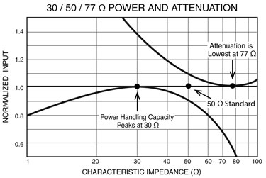
High-frequency connector impedances are typically 50 or 75 Ω. The impedance value for maximum power transfer is 30 Ω while the impedance for theoretical minimum attenuation is 77.5 Ω. High-frequency connectors represent something of a compromise between these two values, since their average is about 50 Ω. (FIG. 2) When long transmission runs are needed, with minimal attenuation, such as in CATV systems, the concern is less with optimizing power transfer, so the higher-impedance 75 Ω connectors are typically used in those systems.
Coaxial connectors are differentiated by gender: jack or female connectors and plug or male connectors. Standard connectors with male and female configurations join in a mated pair. The male contact is a pin and the female contact is a socket. Coaxial adapters make it possible to join connectors of the same sex, or to ease wear on a precision connector used on an expensive test instrument. Such adapters are often referred to as connector savers since they mate to the test connector and also provide a mating end for a cable assembly or coaxial component to be tested, putting the wear on the adapter rather than on the precision connector.
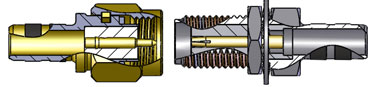
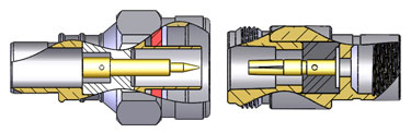
Gendered connectors can be coplanar (FIG. 3) or noncoplanar (FIG. 4), and are usually gender matched in both inner and outer conductors, like Type N and SMA connectors. For a coplanar connector, the center and outer conductors mate in the same plane (such as SMA connectors). For noncoplanar connectors, the center conductors do not mate in the same plane as the outer conductors (such as Type N, BNC, and TNC connectors). Coaxial connectors can be designed with air or solid dielectrics, with polytetrafluoroethylene (PTFE), Delrin®, or thermoplastics serving as common solid dielectric materials. Air serves as the optimum dielectric, followed by PTFE, then Delrin. Connectors with solid dielectrics can be flush or have overlapping configurations, with 75 Ω BNC and 50 Ω SMA and SSMA connectors examples of flush connector configurations. Both 50 Ω TNC and BNC are examples of overlapping connector constructions, which are typically employed to prevent voltage breakdown and handle higher power levels.
Coplanar
Noncoplanar
Comparing Building Materials
Leading suppliers like RF Industries offer a wide range of coaxial connectors and adapters, among them SMA, Type N, 7/16 DIN, QMA, and 3.5 mm connectors. As has been noted, different connectors provide different features and benefits, including size, frequency range, and power-handling capabilities. But RF Industries also provides some connectors, for example SMA or Type N, with a choice of different materials, such as brass or stainless-steel base material, with a variety of finishes, including gold, silver, nickel, white bronze, and passivation. But why so many choices?
It may help to compare some of the different metals used in constructing coaxial connectors to understand their advantages and disadvantages in terms of connector performance. Materials for connectors can be evaluated in terms of their mechanical, electrical, and environmental properties, as well as how well the materials allow attachment to other materials, via soldering, crimping, or other process. Chosen materials should have good electrical conductivity, minimal resistance, good machinability, good stability over time, and good hardness to withstand repeated coupling cycles with minimal wear and performance deterioration. Many metals can suffer from surface corrosion, which can degrade electrical performance over time, so only appropriate metals are used. The choice of materials for a coaxial connector can greatly determine both reliability and electrical performance.
Stainless steel, for example, is a steel alloy with a small amount of chromium content. It is formulated not to rust or corrode when exposed to moisture. It is a hard material that is extremely durable and often used for connector housings, although not for contact parts because of its hardness and relatively low electrical conductivity. It is higher in cost than bronze or brass, but features high stability, high durability, and outstanding corrosion resistance for high reliability in a variety of operating environments. Less durable but lower in cost, brass is also used for connector housings as well as for connector contacts. It is essentially a copper-zinc alloy that is easily machined, being considerably softer than stainless steel. It is an excellent conductor of both heat and electricity, and provides good durability in most industrial and marine environments because it is not subject to corrosion from contaminants found in those environments.
Connector parts are plated with different metals for various reasons, including: to improve the electrical and thermal conductivity, to improve the contact between conductors, and even to improve the solderability or weldability of a part. Noble metals, among them gold and silver, tend to be excellent conductors, and they are resistant to corrosion, but these are expensive materials, so thin layers are used on top of other metals when fabricating connectors. This makes it possible to take advantage of the electrical and thermal properties of the plated metal while using as little of the material as possible.
Gold, for example, is an excellent conductor and it features very good oxidation resistance. It greatly enhances the electrical conductivity of connector parts made from copper or brass. But because of its high cost, gold is plated in thin layers, which can sometimes suffer from diffusion or a wearing away of the gold finish. To minimize gold diffusion, nickel (and sometimes copper) is used as an underplating beneath the gold layer.
Silver is also a fine electrical and thermal conductor, but less expensive than gold. It also can be plated on materials like copper and brass to improve their electrical performance, can carry high current loads with very low loss, and is particularly good at minimizing PIM at high power levels. But, as with gold, silver has its drawbacks, and its main disadvantage is its tendency to tarnish when exposed to some contaminants, including sulphur-based materials and ozone. Fortunately, the effects of tarnishing can be minimized by passivation. Passivation, which can mean different things, usually refers to a process that restores the protective oxide layer to the surface of a metal, making it more resistant to rust and corrosion.
These are some of the metals used in coaxial connector fabrication, and used by RF Industries in the construction of their high-performance SMA, Type N, 7/16 DIN, QMA, and 3.5 mm connectors. The firm’s SMA and Type N connectors are available with either stainless steel or brass housings, with numerous finish types. The SMA connectors can have passivated, nickel, or gold finishes, while the Type N connectors can be passivated or plated with nickel, silver, or white bronze. The white bronze finish offers an alternative to silver, without the tarnish problems, and without the PIM-inducing tendencies of nickel plating. The 7/16 DIN connectors feature brass bodies with silver or white bronze finish, QMA connectors use brass with white bronze finish, and 3.5 mm connectors are constructed of 303 stainless steel with passivated finish to deter corrosion. In the cases where there are choices, it is often a clear tradeoff between lower cost (brass) and higher performance and operating lifetime (stainless steel). But the needs of a particular application may not be that obvious, and specifiers are invited to contact Technical Support for assistance in selecting coaxial connectors with the best combination of base materials and finishes.
Sorting Through Specs
Choosing a connector can be as simple as matching the type of connector already being used in a system, or as complex as evaluating a set of design requirements to find a connector that best meets those requirements. The starting point in specifying a coaxial connector for any RF/microwave design is frequency range, since any connector choice must provide adequate bandwidth for the application. As the table shows, coaxial connectors are available for many different frequency ranges, some broadband, and well into the millimeter-wave frequency range. Most applications will require connectors with a characteristic impedance of 50 Ω, but for those systems operating at 75 Ω, a number of connector types are available, including BNC and TNC connectors, which are typically used in applications below 3 GHz.
Electrically, coaxial connectors are evaluated by a number of different parameters, including maximum insertion loss (IL) and maximum voltage-standing-wave ratio (VSWR) as functions of frequency. The IL for a mated connector pair is simply 10log10(PR/PT), where PT is the power transmitted (or applied to a connector) and PR is the power received from the connector after losses. The maximum IL for a mated connector pair as a function of frequency, F (in GHz), can be found from the simple relationship:
SMA 15' Cable Assemblies
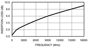
Maximum IL = X( F )0.5where X is a multiplication factor which varies from connector to connector pair
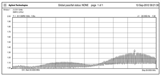
VSWR ratio of maximum and minimum voltages on a transmission line caused by combination forward and reflected wave:
VSWR = [1 + (Pr/Pf)0.5]/ [1 - (Pr/Pf)0.5
where
Pr = the reflected power (in W) and
Pf = the forward power (in W)
Maximum VSWR can also be found as a function of frequency for a given mated connector pair from the relationship:
Maximum VSWR = Y( F )0.5
where Y is a factor that will yield some value of maximum VSWR,
such as 1.02 + 0.1( F )0.5 which is 1.22:1 at 4 GHz and 1.32:1 at 9 GHz
Additional coaxial connector electrical parameters include maximum operating voltage (in VDC), insulation resistance (in MΩ), dielectric withstanding voltage, operating temperature range, and operating lifetime, in maximum number of matings. Some connectors, such as 7/16 DIN connectors, are designed for low-distortion performance, in particular low passive intermodulation distortion (PIM). High PIM can impact the performance of communications systems that rely on digital modulation formats, and these specially characterized connectors can ensure minimal levels of connector PIM. The PIM characterization is usually applied to any coaxial cables as well, with the connectors considered as part of the system’s cable assemblies.
All connectors have a finite operating lifetime, and any connector’s operating lifetime is specified by the number of mating cycles. No matter how well designed, a connector will eventually wear out and its performance will degrade with extended use. Connections and disconnections result in wear and tear on any connector.
Some connector types are compatible with others, a trait that can serve well in some test-and-measurement applications. For example, SMA connectors tend to be compatible with 2.92 and 3.5 mm connectors, although they may not provide the full frequency range of those smaller connectors. Stainless steel connectors with air dielectrics are typically designed for 500 mating cycles, in comparison to a lesser number of mating cycles for most SMA connectors. Smaller, higher-frequency connectors, such as 2.4, 1.85, and 1 mm connectors, do not cross-mate with SMA connectors, however. Especially for measurement applications, repeatability between different (although compatible) connector types can be achieved by using a torque wrench and maintaining a standard amount of torque, such as 8 to 12 in.-lbs. for most RF/microwave connectors. It is important to note that insufficient coupling torque can result in degraded RF/microwave performance, while too much torque can damage a connector and shorten its operating lifetime.
Connector suppliers like RF Industries characterize their connectors as mated pairs using microwave vector-network-analyzer (VNA) systems with wideband RF/microwave signal generators to measure forward and reverse power levels (i.e., transmission and reflection) through the mated connector pair. Additional test equipment, such as broadband power amplifiers, is also employed for evaluating maximum power levels through the connectors.
Designers should be aware that some connector suppliers offer connectors in three different grades: commercial grade (for production and general-purpose use on standard components), general precision grade (as used on instrumentation and test equipment), and laboratory precision grade (for calibration and measurement standards) (FIG. 6). In many cases, the tighter tolerances required by some demanding applications can be met by one of these different grades of coaxial connector.
Precision SMA Cable Assembly
Design engineers should let their list of electrical and mechanical requirements, including frequency range, insertion loss, VSWR, and performance in terms of operating temperature, shock, and vibration, help guide their choice of coaxial connectors. In addition to the starting electrical points of frequency, IL, and VSWR, specifiers consider not only how many mating cycles will be required, but the effects of shock, vibration, and operating temperature on the connector’s performance contributions to a system. Another consideration is which special connector configuration, such as crimp, clamp, PCB, or panel-mount connector, might be available for a particular application. Not to be forgotten, cost should also be factored in when considering the different benefits of a particular coaxial connector choice.
As an example of a selection process for a design operating to 10 GHz, connectors under consideration would include Type N and SMA connectors, based on their operating frequency ranges. Both are 50 Ω connectors, with excellent electrical characteristics. The Type N connector exhibits maximum IL of about 0.2 dB with maximum VSWR of 1.30:1 at 10 GHz. The SMA connector has the same IL performance, with lower maximum VSWR of about 1.25:1 at 10 GHz. Both are rated for 500 minimum mating operations and operating temperature ranges as wide as -65 to +165°C. The larger Type N connector achieves lower RF leakage at higher voltage and power than an SMA, at -80 dB compared to -60 dB for the SMA. The Type N connector is also rated for higher working voltage, at about 1500 V compared to about 500 V maximum for the SMA. In the case of this comparison, system requirements for high voltage and low RF leakage would put the choice in favor of the Type N connector. In addition, when a connector is being considered as part of a cable assembly, and a performance parameter such as power-handling performance (such as for a transmitter application) is a key consideration, it will be limited by the combination of the connector(s) and the cable. (For more on specifying coaxial cable assemblies, refer to the free white paper soon to be available from RF Industries.)
In Summary
Coaxial connectors range from DC through millimeter-wave frequencies and are available for RF/microwave applications through 125 GHz. Some high-frequency connectors increase in cost as they decrease in size. Connectors are available in grades from commercial to high precision. By carefully considering the needs of an application, however, the right connector can be found to best match that connector’s set of tradeoffs to that application.
| Comparing connectors: from audio to millimeter-wave frequencies | |||
|---|---|---|---|
| Connector Type | Frequency Range | Coupling | Impedance |
| RCA | DC to 10 MHz | push on | 75 Ω |
| UHF | DC to 300 MHz | threaded | 50 Ω |
| BNC | DC to 4 GHz | twist-lock | 50, 75 Ω |
| TNC | DC to 12.4 GHz | threaded | 50, 75 Ω |
| TNC | DC to 12.4 GHz | reverse threaded | 50 Ω |
| Type N | DC to 11 GHz | threaded | 50 Ω |
| Type N | DC to 11 GHz | reverse threaded | 50 Ω |
| SMA | DC to 18 GHz | threaded | 50 Ω |
| SMA | DC to 18 GHz | reverse threaded | 50 Ω |
| SMB | DC to 4 GHz | snap on | 50 Ω |
| SMC | DC to 10 GHz | threaded | 50 Ω |
| SSMA | DC to 40 GHz | threaded | 50 Ω |
| C | DC to 10 GHz | twist-lock | 50 Ω |
| SC | DC to 11 GHz | twist-lock | 50 Ω |
| 7 mm | DC to 18 GHz | threaded | 50 Ω |
| 3.5 mm | DC to 34 GHz | threaded | 50 Ω |
| 2.92 mm | DC to 40 GHz | threaded | 50 Ω |
| 2.40 mm | DC to 50 GHz | threaded | 50 Ω |
| 1.85 mm | DC to 65 GHz | threaded | 50 Ω |
| 1.00 mm | DC to 110 GHz | threaded | 50 Ω |
| 0.8 mm | DC to 125 GHz | threaded | 50 Ω |
Dave McReynolds, Director of Engineering, RF Industries