Choosing The Right RF Cable Assembly
Download PDFCoaxial cable assemblies are almost everywhere electronic systems can be found. And they have a simple job: to serve as a signal path to transfer signals from one location to another. But they must do that job without fail and with little or no change to the signals, whether they are high-frequency analog signals or high-speed digital signals. Because coaxial cable assemblies are so vital to such a wide range of systems, from rugged ground-based electronic systems to orbiting satellites in space, the selection process for those cables should not be treated lightly. Choosing the right coaxial cable assembly is not a trivial task, but it is one that can be made somewhat easier by better knowing what to look for in a high-frequency or high-speed coaxial cable assembly.
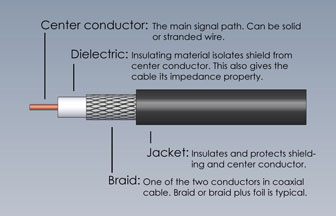
Coaxial cables provide the means of transverse-electromagnetic (TEM) mode of transmission. The name coaxial comes from their construction, which typically consists of a bare copper round wire inner conductor, solid or stranded, surrounded by a tubular dielectric insulator, which is surrounded by a tubular outer conductor or shield, which in turn is surrounded by some form of protective outer layer, usually a plastic layer. The coaxial cable is the brainchild of British mathematician Oliver Heaviside, who patented the concept in the late 19th Century. He had been studying skin effects in telegraph transmission lines, determining that wrapping some form of insulator around the transmission line would improve its performance. The first commercial use of a coaxial cable in the United States was a 220-mile-long run of coaxial cable between two towns in Minnesota, from Stevens Point to Minneapolis, nominally for telephone lines.
For effective use with high-frequency analog signals or high-speed digital signals, the dimensions of the different parts of a coaxial cable must be precisely controlled to achieve constant conductor spacing. The coaxial construction (Figure 1, cutaway view of coax cable) confines the electric and magnetic fields of conducted signals within the dielectric insulator while preventing electric and magnetic fields outside the outer shield layer from interfering with conducted signals. A coaxial cable becomes an assembly when it is terminated in a customer’s choice of coaxial connectors. Coaxial cable assemblies are commonly used in cable-television (CATV) installations, for high-frequency RF/microwave connections, in precision test and measurement equipment and systems, and for transferring high-speed digital signals in computer networks.
Coaxial cable assemblies for high-frequency analog or high-speed digital applications typically have characteristic impedances of either 50 or 75 Ω, and these impedances are not by chance. The two values trace back to pioneering work performed at Bell Laboratories in 1929. Those early experiments sought optimal characteristic impedances for transferring high power levels as well as for achieving minimal signal loss. Ideally, the same characteristic cable impedance would support both conditions, but that is not the case. A characteristic impedance of 30 Ω was found to be optimal for transferring signals at high power levels, while 77 Ω was found to be well suited for minimizing the loss of high-frequency, high-speed signals. The Bell researchers also found that 60 Ω was the best characteristic impedance for high-voltage signals. The 50 Ω impedance was chosen as a practical compromise between the power-handling capability at 30 Ω and the minimal attenuation at 77 Ω, while 75 Ω was selected as a good match for a center-fed dipole antenna in free space for use in radio systems.
When specifying a coaxial cable assembly, it helps to understand the electrical and mechanical parameters of different cable types and how to compare them. RF/microwave coaxial cables can be grouped into three categories: semi-rigid and conformable (or hand-formable) cables, flexible cables, and corrugated cables. Each is constructed differently, with different mechanical characteristics and different levels of electrical performance.
Semi-rigid cables, so called because they offer more flexibility than rigid cables, are known for their excellent electrical performance but limited formability. Because of their lack of flexibility, they usually require the use of three-dimensional (3D) engineering drawings for proper integration into most electronic systems. But choosing a coaxial cable assembly involves trade-offs, and for the sacrifice in flexibility, semi-rigid cable assemblies provide superior electrical performance compared to the other two coaxial cable types, and offer uniform impedance, low insertion loss over wide frequency ranges, and excellent shielding effectiveness (SE, a parameter that characterizes both cable leakage and susceptibility to outside electromagnetic sources).
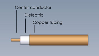
Semi-rigid cables are typically constructed with a solid center conductor surrounded by a dielectric insulating material, covered by a solid tubular outer conductor (Figure 2, a cutaway view). The center conductor is usually silver-plated copper, which is nonmagnetic and supports low-loss performance. The outer conductor is typically formed of aluminum or copper, which is bare or plated with tin. In contrast to rigid cables, semi-rigid cables are typically characterized by the cable outer diameter: 0.034, 0.047, 0.086, or 0.141 inches. Small-diameter semi-rigid cables can support operating frequencies as high as 110 GHz, but with maximum power-handling capabilities of a few hundred watts and typically much less. Rigid cables, in comparison, have outer diameters ranging from 0.875 to 8.1875 inches. They offer power-handling capabilities of kilowatts at lower frequencies, typically through about 800 MHz for applications such as commercial radio and television broadcast transmitters.
The solid outer conductor provides excellent SE performance in semi-rigid cables, with some sacrifice in flexibility. The high shielding values enable semi-rigid cables to achieve excellent electrical performance even in environments with high-level signals, near transmit antennas. Using different configurations for the outer conductor, manufacturers of coaxial cables have improved the flexibility of their cables while still achieving high SE levels. The outer conductor or braid layers have been designed with flat metal wraps, round metal wraps, strips of metal with and without coatings, and in single-layer, double-layer, and triple-layer configurations to provide a wide range of SE values with low insertion loss while also achieving some measure of flexibility in the cable.
Conformable cables offer a great deal of the electrical performance of semi-rigid cable assemblies, but with somewhat more flexibility to ease difficult installations and connections. Conformable cables are not designed for repeated flexure, but can be bent (within the limits of their minimum bend radius) to a required shape and will retain that shape once bent. For good electrical performance, conformable cables are constructed with silver-plated copper conductors or silver-plated, copper-covered steel conductors and a copper-tin-composite shield design that provides high SE.
Flexible cables sacrifice some of the electrical performance of semi-rigid cables, but their greater flexibility simplifies installations in systems. In place of the solid conductor of a semi-rigid cable, a flexible cable often employs a stranded center conductor. Instead of the semi-rigid cable’s solid outer conductor, a flexible cable uses a polyurethane or fluorinated ethylene propylene (FEP) outer jacket. A number of different dielectric insulator materials may be used in a flexible cable assembly, including polyethylene, solid polytetrafluroethylene (PTFE), and high-density polyethylene foam. The foam’s air content lowers the dielectric constant of the insulator material while helping reduce cable attenuation.
For example, a flexible coaxial cable might use an outer conductor formed of silver-plated copper wires braided over the insulator, or silver-plated copper strips in a basket weave or silver-plated copper wires set parallel to each other and in a long spiral configuration. The center conductor may be solid copper, to minimize cable loss, or stranded, for applications that may require repeated flexing of the cable, albeit with higher loss than cables with a solid center conductor.
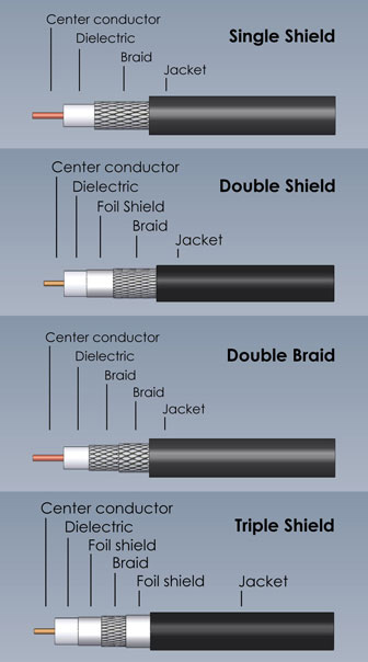
The braid layers in flexible coaxial cables allow very good flexibility when combined with a center conductor and outer jacket that also support flexure. Because a wire braid has air gaps between strands in the braid pattern, shielding is not continuous. The size of the air gaps can increase with flexure, compromising SE at those spots in a single braided cable. To ensure high SE, additional braid layers, including helical and/or ribbon braids, may be added to form a double-shielded or triple-shielded cable with more continuous shielding coverage (Figure 3). The tradeoff when choosing a thicker braid with two or three layers is additional stiffness and loss of flexibility in the cable. Cable manufacturers use percentage of shielding coverage in their specifications to indicate the effectiveness of shielding in a cable assembly.
Braids for coaxial cables are available in a range of materials and types, with each representing trade-offs. A braid layer formed of round wire provides good flexibility and has the lowest material cost but, as noted earlier, can suffer performance degradation with flexing. More sophisticated braid materials represent increased material costs, but more consistent performance over time. For example, a shield formed of flat metal ribbon can deliver low cable attenuation with high SE performance, while maintaining consistent electrical performance over time. A helical flat braid supports good flexibility, while also enabling excellent phase stability with cable flexure and high SE levels. A wrapped or folded foil braid can also provide high electrical performance, with good mechanical strength but with some loss of flexibility compared to other braid configurations.
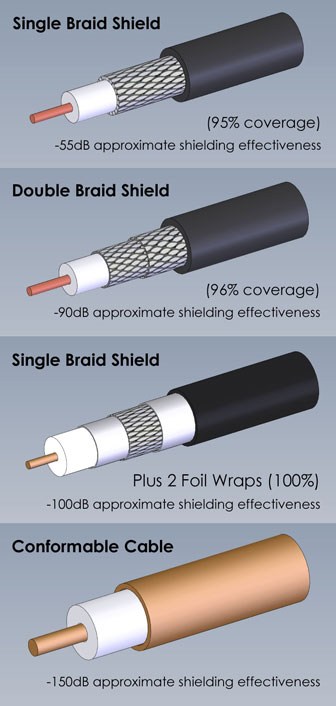
The number of braids will impact both flexibility and SE. Depending on the shield material, like copper wire braid, and whether it is silver coated, a coaxial cable with a single braid layer can deliver SE of 40 dB or higher with very high flexibility. With each added braid layer, the cable’s flexibility decreases as the SE increases. A double braid layer formed of two round-wire braids can typically deliver better than 60 dB shielding. But if a foil shielding or woven flat braid is used for one of those braid layers, the SE can be increased to 90 dB. Double-shielded cables using a foil shield under a tin-filled composite layer can achieve better than 100 dB SE while still achieving reasonable flexibility. High SE values are possible with triple-shielded cables that combine round wire and woven flat braid layers, although with some sacrifice in flexibility (Figure 4).
Coaxial cable assemblies are defined by not only the type of cable but by the coaxial connectors on either end of the assembly. For the best application match, the different cable types can be compared by means of standard electrical and mechanical parameters, but such comparisons should always compare similar lengths of cable with similar coaxial connectors at both ends of the cable assemblies being compared.
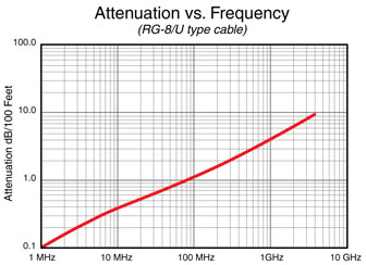
In terms of amplitude and phase characteristics, a coaxial cable assembly should be electrically invisible within a system, providing a signal path between two points in the system with minimal effects on the transferred signals. In the real world, however, cable assemblies can make alterations to the signals they carry, although a proper choice of cable assembly can help minimize these effects. Cable assemblies are typically characterized by a number of different electrical and mechanical parameters (Figure 5): cutoff frequencies, attenuation or insertion loss (in dB/ft. or dB/m), return loss or voltage standing wave ratio (VSWR), capacitance (pF/ft.), velocity of propagation (VP, in %), power-handling capability (in W), and even weight (lbs/ft. or lbs/m). These different parameters can provide useful yardsticks for comparing cable assemblies from different suppliers.
Probing Performance Parameters
As mentioned previously, coaxial cable assemblies of all types are defined by their characteristic impedance, typically 50 Ω for RF microwave and high-speed data signals and 75 Ω for UHF, VHF, and video signals. The characteristic impedance determines the amount of power transfer and attenuation along the length of a cable and controls the amount of reflected and standing waves. It is usually denoted as Z0, which is determined by the dielectric constant or relative permittivity of the inner insulator material, the radius of the inner conductor, and the radius of the outer conductor. Ideally, a coaxial cable assembly should maintain closely matched impedance between a source and load for maximum power transfer and minimum VSWR.
For example, VSWR is the ratio of the maximum effective voltage to the minimum effective voltage measured through a coaxial cable assembly at a specific frequency. Given as a ratio to unity, such as 1.30:1, the value generally increases with frequency. The lowest possible values, which are representative of cables with low reflections and return loss, are desirable.
For minimal reflections, the characteristic impedances at all connections, including where the coaxial connectors are joined to the cable, should maintain a tight tolerance. When a high-frequency or high-speed signal traveling through a coaxial cable encounters an impedance mismatch, some portion of the signal will be reflected back to the source. These low-level reflections are measurable as return loss or VSWR using suitable instrumentation, such as a vector network analyzer (VNA). Multiple impedance discontinuities along a cable can be additive, resulting in higher return loss and phase distortion.
In addition to matching a system’s characteristic impedance, a coaxial cable assembly must provide sufficient frequency range for an application of interest. Frequency limits will be determined by the combination of the connectors and the cable, and usually specified in terms of the maximum operating frequency, or the cutoff frequency of the connector type, the cable, or the assembly as a whole. For a given coaxial cable diameter, a number of different connector types are available, in different configurations (such as straight or right-angle types), and the frequency ranges can vary widely for these different connector types. (For a more detailed discussion on coaxial connectors, please refer to the white paper, Optimize Your RF/MW Coaxial Connections) When considering various cable/connector assemblies for an application, the cutoff frequencies of both the cable and connectors should exceed the highest operating frequency of the application by at least 10%.
The speed at which signals travel through a coaxial cable assembly is its VP parameter, which refers to the transmission speed of electrical energy through the cable as a percentage of the speed of light. A cable assembly with VP of 83%, for example, transmits electrical signals at 83% the speed of light. This parameter is of particular interest in systems with multiple signals and cables in which the timing is critical, where delays in any of the signal line relative to the others cannot be tolerated.
Some applications may also specify time-domain characteristics for a cable assembly, in terms of a nominal time delay for a length of cable, usually specified in nanoseconds per meter of cable. This parameter can be measured for a cable or cable assembly according to the military specification MIL-C-17, using a time-domain reflectometer (TDR) with the appropriate frequency range to cover the frequency of interest.
For most applications, a cable’s outer conductor or shield layer is maintained at a system’s ground potential and voltage is applied to the inner conductor to transfer signals. The electromagnetic (EM) energy is contained within the coaxial cable assembly, with very little leakage. A coaxial cable assembly also suffers very little interference from outside EM energy sources.
Amplitude and phase are the basis for several key cable assembly performance parameters, including attenuation or insertion loss, return loss, and phase stability. These characteristics are largely a function of the building materials for a cable, such as the type of center conductor, dielectric, and even braid materials that are used to construct the cable. High-quality materials, such as silver-plated copper center conductors, will provide the best electrical performance, with the trade off of higher cost.
For flexible cables, there is also concern over amplitude and phase stability with flexure—how much a cable’s amplitude and phase characteristics change as the cable is bent or flexed. Every flexible coaxial cable is defined by a minimum bend radius, which is the smallest radius around which a cable can bend without any adverse effects, and which should never be exceeded. Because the outer conductor has a larger diameter than the inner conductor, and maintaining a constant distance between the two is difficult with flexure, some change in a cable’s amplitude and phase is inevitable with flexure, but it should be minimal and predictable. The amplitude stability is like phase stability in being referenced to a particular test frequency, and can be evaluated with a microwave VNA.
When using a VNA, both amplitude and phase stability for a cable assembly can be determined by bending a cable under test around a precision mandrel of known circumference and making amplitude and phase measurements of the cable in its bent and straight states. Some cable manufacturers may also provide cable parameters known as amplitude and phase repeatability with flexure, which is a measure of the predictability of the change in the cable’s amplitude and phase with flexure. These parameters can be measured following repeated flexures on the mandrel; the desired results are the smallest phase deviations possible.
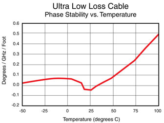
Because a cable’s amplitude and phase characteristics are affected by temperature, when comparing cable assemblies, values for amplitude and phase stability or repeatability should always be referenced to the same test temperature, which is typically room temperature or +25°C. Additional performance parameters, amplitude and phase stability with temperature, can provide insight into a cable assembly’s expected behavior over a temperature range of interest.
Some applications may require multiple cable assemblies with closely matched amplitude and/or phase characteristics, known as amplitude-matched or phase-matched sets of cable assemblies. Such cable assemblies are critical to the performance of phase-sensitive systems, such as phased-array radars, for example. Cable suppliers typically characterize the amplitude and phase responses of matched cable assemblies over a standard wide temperature range, such as -55 to +200°C, or a temperature range specified by a customer, to ensure that the cable assemblies exhibit similar changes in amplitude and phase with changes in temperature—with all of their amplitudes and phases changing together as the temperature changes. It is important to note that the terms amplitude-matched and phase-matched sets of cable can refer to absolute or relative phase in a system. Cable sets supplied as absolute phase-matched sets are manufactured and tested to be within absolute electrical values and tolerances, and every cable in the set must meet the criteria. Sometimes called infinite phase-matched cable sets, another absolute phase-matched set of cables will be within the tolerance of any early absolute set. In contrast, relative matched sets match to each other within a required set of limits, but one relative matched set of cables may not match in amplitude and or phase to another relative matched set of cables. For any phase-matched sets of cable assemblies, the tighter the phase window, the more difficult the manufacturing process and the more expensive the cables will be.
A coaxial cable assembly’s operating temperature range is very much a function of the materials used to produce the assembly. Some cable assemblies are specified for operating temperature ranges as wide as -55 to +250°C while assemblies with an FEP outer jacket are generally limited to a high temperature of +200°C. Changing temperatures result in the expansion and contraction of the materials used in a coaxial cable assembly, and can be accounted for by means of careful measurements across the operating temperature range to ensure that the cable’s amplitude and phase variations remain within expected limits (Figure 6).
One temperature-related parameter for coaxial cable assemblies that is not so predictable is thermal shock, which is how a cable assembly behaves with a rapid change from one temperature extreme to another. Cable manufacturers typically specify an operating temperature range for their assemblies, but they cannot know how those assemblies will respond to the many different cases of thermal shock without knowing the particular temperature extremes and rate of temperature change. However, for applications where it is a concern, cable suppliers can generally characterize a cable assembly for thermal shock per the test requirements set forth in military standard MIL-STD-202, Method 107.
Fitting Cables to Applications
Having a set of performance parameters to compare cables from different suppliers can be useful in determining the best value in a coaxial cable assembly. However, the needs of each application will usually dictate the particular requirements for a cable assembly or set of cable assemblies. Even assuming a common characteristic impedance, such as 50 Ω, electrical and mechanical cable requirements can vary widely from system to system, such as the importance of cable weight in airborne systems versus ground-based systems, the types of connectors needed to mate to the system, the operating frequency range, the operating temperature range, and the power-handing capability, to name a few.
Perhaps a good starting point for specifying a cable assembly for a given application is to decide on the connectors. The connectors will not only set limits on the performance of the cable assembly, such as frequency range and power-handling capability, but they will also determine the range of usable coaxial cable diameters. A larger-diameter cable, for example, will support termination with Type N connectors while a smaller-diameter cable might serve as a better match for a smaller connector, such as an SMA connector. The Type N connector provides excellent electrical performance through 11 GHz, while the SMA typically exhibits the equivalent attenuation and return-loss performance through 18 GHz. The larger-diameter cable with Type N connectors will have much higher voltage-withstanding and power-handling capabilities than the smaller-diameter cable with SMA connectors, although its larger size will result in greater weight per foot of cable assembly.
In some applications, notably in commercial communications systems using digital modulation, the intermodulation-distortion (IMD) performance of a coaxial cable assembly can be a critical parameter. It is usually compared in terms of the cable’s passive intermodulation (PIM). Excessive PIM is usually apparent for a communications standard in terms of degraded bit-error-rate (BER) performance. The PIM levels of different coaxial cable assemblies can be compared in relative terms, but there are no current industry standards for PIM to serve as an absolute reference. It should be noted that acceptable PIM levels for cable assemblies are somewhat arbitrary, and that measured values can vary depending upon the test method and environment.
In meeting the needs of an application, other cable assembly parameters to consider are whether the application is indoors, outdoors, airborne, space borne, or in a test laboratory. The location of use can have requirements that call for a coaxial cable assembly with specific materials. For example, a cable meant for outdoor use typically requires an outer jacket composed of some form of plastic or thermoplastic for environmental protection. The outer jacket for a cable meant for outdoor applications may require resistance to oxidation or to ultraviolet (UV) light. Also, some locations may require cable assemblies with outer jackets of fire-resistant materials.
In Conclusion
Many cable suppliers, including RF Industries, offer a large selection of cable assemblies and connectors, supplying cable assemblies with a customer’s choice of connectors and length. A cable supplier can guide a customer in terms of particular cable types and connectors for an application based on electrical and/or mechanical requirements like frequency range, power-handling capability, loss, flexibility, and operating temperature range. A commercial telecommunications or CATV application may be best served by 75 Ω cable assemblies with BNC or TNC connectors, while a need for flexible cables in a test laboratory might best be filled by low-loss cables with precision SMA connectors. Each application is different and unique, and a cable and connector supplier can provide much needed insight as part of the cable selection process.
As an example, deep-space systems are among the most demanding applications for coaxial cable assemblies. Such applications require light-weight cables without compromising power-handling capability. Space-qualified cable also typically requires high radiation resistance, and typically must meet or exceed NASA outgassing requirements. They also may require a construction with high bend and crush resistance. In specifying coaxial cable assemblies for deep-space missions, these special requirements are added to the usual list of requirements for frequency range, attenuation, return loss, VSWR, and other standard electrical and mechanical requirements. In some cases, cable assemblies might even need to comply with Restriction of Hazardous Substances (RoHS) directives to limit or eliminate the amount of any sensitive materials, such as cadmium, lead, mercury, and chromium.
For military applications, coaxial cable assemblies must meet the requirements of numerous standards, including MIL-C-17, MIL-DTL-87104, and MIL-C-39012. Acceptable guidelines for cable materials, including the center conductor, the dielectric, the shields, and the outer jacket are set within MIL-C-17. The standard also provides details on cable performance testing, i.e., dielectric withstanding voltage.
Different applications call for different performance from a coaxial cable assembly or set of assemblies. When specifying standard coaxial cable assemblies or custom assemblies, some cable assembly suppliers can provide practical guidance on the optimum combination of coaxial cable and connectors to meet specific electrical and mechanical requirements for a customer’s operating frequency band and temperature ranges.
Dave McReynolds, Director of Engineering, RF Industries