Bulletproofing the Critical Connection
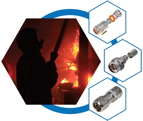
What You Need To Know About RF Connectors For Critical Communications Applications.
Manny Gutsche,
RF Industries
Introduction
There are two axioms that tend to be true across technologies, industries, platforms, ecosystems-just about anything. The first is that no matter what type of infrastructure is on the radar screen, it is only as good as its weakest link. The second is that if there isn’t enough time or money to do it right the first time, there is always enough time to do it over. When dealing with RF connectors, these two axioms not only have a significant effect on system performance, but on the bottom line as well. Understanding the critical nature of RF connectors, and what it takes to make sure they don’t become the weakest link, is tantamount to optimal RF system performance.
Minimizing human error when it comes to connector installation saves time, money and headaches. And understanding of the metrics of connectors and how to make foolproof connections is a must for any field installation.
Focus on the connector
It may seem that the RF connector is a plug-and-play component that hasn’t changed much in decades, or that it takes very little skill or knowledge to install an RF connector correctly; in reality, however, these are misconceptions. Physically they may look the same year after year, but technology marches on in connectors just like it does elsewhere.
While the more complex components, such as TX/RX modules, system components in the TX/RX path, or control systems such as the OS and support hardware, often have backup or fall-over schemes, connectors do not. If a connection goes bad, which generally is caused by improper installation, the ramifications can be anything from slight changes in VSWR to complete failure of the transmission path it is located in. And often, finding and correcting the problem is difficult, especially if the failure is subtle and related to environmental factors. They are the critical link between the high-cost components in the RF Path. Statistically, connectors only account for about one percent of the total cost of the wireless system. But it can be argued that they are the most significant and important component. They are what link the these high-cost components to the wireless ecosystem.
Connector metrics
Connectors serve a wide range of functions in a wireless system. Some are micro; other macro. Some carry light, others power, others RF. The RF connector that will be the subject of this discussion.
The most important metric of connectors is the understanding of how they attach to a system. Connectors can be integrated into the various system components, or be stand-alone with cables connected to each end. Regardless, each connection requires the same diligence to ensure there is no integrity breach at the installation.
Each connector type has a specific set of specifications and properties. These are things like MIL spec, propagation delays, dielectric constants, characteristic impedance, contact resistance, frequency range, VSWR, voltage rating, etc. While the particular metrics of these may not be of interest for a typical installer, each affects the performance of the connector to some degree. Therefore, a fundamental understanding of such metrics is essential.
In the near future, connectors will become an even more critical element due to the deployment of wireless communications in the mm wave bands. Higher speeds, increased bandwidth, greater density and smaller sizes are all metrics driving next-generation connector technology. If 5G and the Internet of anything (IoX) come to pass as anticipated, it is quite possible that the connectors design bar may be set to cover DC to 18 to 28 or even higher frequencies in a single package. Further, we may expect demand for connectors to be smaller, more robust and fool-proof in terms of installation.
Making the connection
There are a number of parameters, processes and procedures applicable to connector field installation. The rest of this paper will drill into aspects of making the perfect, optimal connection.
Basic connection philosophy
Because connectors have a long history, there is a deep well of knowledge that can be drawn upon to forge optimal connections. Proper connector installation insures that there are no incongruences in the connection. Let’s examine the elements that surround that.
A number of pain points and considerations affect connector integrity. First of all, when making a connection, the integrity of the system must be verified. If there are issues with cabling, equipment, environment, etc., there is no way to ensure the connector is functioning properly. Installing a connector in a faulty system can lead to endless complications within the wireless network, some of which include:
- Intermittent operation
- Out of spec performance
- Improper connector installation
- Improper cable or termination equipment
- Contamination of the connector and cable
Each of these pain points needs to be considered before the connectors are installed. Simply put, the operational status of the system has to be verified to insure proper connector operation. Of course, there are circumstances in which the system isn’t operational at the time of the installation (new deployments, for example, or retrofits). At this point, the best practice is to make sure the variables at the connection point are correct. So long as best practices are followed, connectors may be ruled out as a cause for faults in the network.
Component preparation
There are two basic preparatory processes that revolve around connector installation-cable preparation and connector preparation. Cable preparation involves making sure the cable is uncompromised by kinks, cuts, dents, water, pressure, etc. Once the cable is known to be good, it is ready for preparation. While it may seem that cable or connector preparation is a no-brainer, there are some subtleties that can sneak in and weaken the connection.
First, it is important to get a clean cut on the cable. Sloppy cuts can cause poor mating between the cable and the connector, causing impedance, PIM, leakage or other problem to arise.
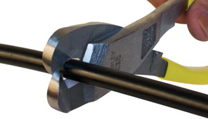
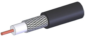
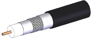
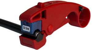
Because RF cables vary widely in construction and components—from a simple three element braided shield (see Figure 1) to a four-element, or higher multicomponent coax (see Figure 2). It is imperative that the right tool(s) is used to prepare the ends. There are a number of tools that can do that, which one is used depends upon the cable. It is further imperative to ensure that the cable remains round and isn’t compressed by the cut. The end result should be a clean cut/strip made with sharp tools that won’t leave any frayed edges or shield remnants.
Once the cut is satisfactory, select the proper tool to strip it. Again, this depends upon the type of cable being used. While this may seem like a trivial point, it is important that a firm grip on the cable is affected. Correct stripping of the cable is one of the more critical considerations, and using the wrong tool or movement during stripping can affect the connector’s mating precision. The same care should be taken when stripping the inner conductor. Also, avoid nicking the inner copper conductor. If the inner conductor is braided, be sure none of the individual braids are cut. Proper fit into the connector requires all strands to be intact.
Finally, insure that all parts of the cable are free of contaminants, such as oil, grease, dirt, etc. Once this is deemed satisfactory, the next step is to select the proper connector.
The connection
Because there are many different types of RF cable and connectors, it would be impractical and too lengthy to discuss each of them. Therefore, the discussion will be held to topics that can be applied, across-the-board, to most cases.
The first step is to select the proper connector for the cable. Next, the technician needs to prepare the cable. Once this has been done, (technically the connector should be selected first as the strip dimensions will vary), the next step is to make the connection. There are three basic ways to do this: Solder/clamp, crimp and compression.
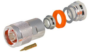
Solder/Clamp method
Most RF clamp connectors that are considered solder are really solder/clamp. This is because the center pin is soldered and the braid is clamped by a series of rings, a washer and a nut.
This method is the most reliable. However, that reliability comes at a price – knowledge. Soldering is a technique that has a learning curve to do properly so there is a proficiency level the technician must achieve.
Soldering has a number of advantages. As previously mentioned, soldering is the most reliable connection method. It is also the longest-lasting and least likely to deteriorate with age. It is equally as reliable with both solid and stranded cables. Soldering takes only a soldering iron and solder. Simply clamp the connector in a vise, heat and solder.
The major disadvantages include time and skill. Soldering takes the longest, and it requires a skilled technique. Among other things, a poor soldering technique commonly results in a “cold” solder joint, a joint in which the components are insufficiently heated and the solder fails to liquefy as required to flow into the strands and completely adhere to the conductor. As it cools, it will contract and voids will occur between the two components. This will eventually fail-either by complete separation or incongruences that will affect the signal continuity as it passes through. This is especially problematic at higher frequencies.
It is critical that the proper temperature and solder be used so the joint can be appropriately heated. If this isn’t done, the solder flow will be inconsistent throughout the joint. And, if not done correctly (i.e. if too much heat is applied), there can be damage to the conductor shield or dielectric. Also, if the joint isn’t held immobilized until all the components have cooled, micro cracks can develop in the solder, which will also eventually lead to solder fatigue and joint failure.
A word of warning with solder joints; never crimp a solder joint. Solder has no compression dynamics and will just weaken.
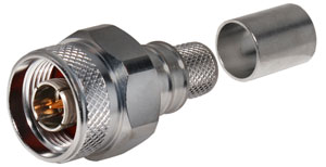
Crimp method
This method is the most common. It is quick and efficient, but also requires a bit of skill. Its major advantage is efficiency. Further, it requires no heat or soldering tools.
Crimping takes a fraction of the time it takes to solder. If a large number of connections are required, it is the go-to method.
Crimping can be very reliable-as reliable as a solder/crimp operation, but only if done properly. Crimp connectors offer the best resistance to pulling. In that sense, they are the strongest type of connector. The trick here is to get the crimp so it deforms the metal sufficiently past the yield point, yet not so much as to negate the “spring back” action that holds the connection in place. Crimp connections are often referred to as “cold welds.” They can be done on solid and stranded conductors with equal reliability, but they are more difficult on solid wire.
Crimping’s major disadvantage is thermal. If done incorrectly, the coefficients of expansion between dissimilar metals can compromise the contact between the cable and the connector. This is an important consideration in abnormally hot or cold environments. Also, if the connection becomes compromised for any reason, it can leak significant levels of RF and that can interfere with surrounding equipment.
Crimping has other issues as well. If the crimp isn’t linear all around the interface the stresses on the connection can cause distortion of the components, or breakage of the joint. The same holds true for deforming the components via improper alignment – over/under crimping, or incorrect positioning of the components when crimping. Under such conditions the contact will not seat properly and will be out of spec. This will affect signal continuity, which will present itself in VSWR, intermod, etc.
Unlike soldering, in which the connection can be redone, once the crimp is made it is final. If the crimp is unsatisfactory, the whole joint must be scrapped and redone from the beginning. Further, though it is rare, a crimp joint may occasionally become loose under frequent flexing, even when properly made.
Crimping requires a degree of finesse. Since it is a mechanical connection, here isn’t much margin for error. The connector must be the proper size, the conductor(s) must be positioned correctly and there must be the correct ratio of ferrule stud ID to cable dialectic OD. Further, the crimp must have the proper tension applied to prevent unequal pressure and distortion of the materials.
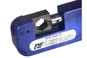
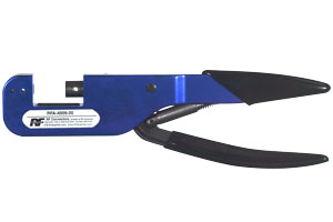
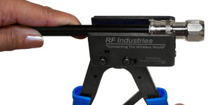
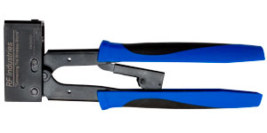
Finally, the coup de gras of crimping are the tools. More than anything, the proper set of tools is required to make good crimps. A number of great tool sets are available, offering the various-sized dies and accessories required to make a clean, professional connection.
Compression method
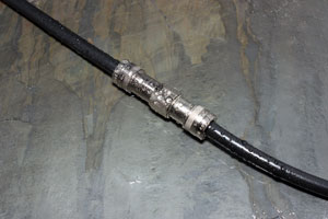
Compression connectors are also fast becoming the predominant choice for RF cable terminations, although they are a bit of a niche. Compression fittings are the most expensive, but they offer one significant advantage—compression connectors result in a compressed seal at the connector that is airtight and watertight. This makes them a good choice for harsh outdoor or indoor environments where elements are a metric. And they are relatively quick, easy and foolproof, which is very appealing for critical applications.
Compression connectors are held on by tightening a collar to make the connection rather than crimping it permanently in place. Another advantage is that compression generally requires the least amount of expertise but has some sophistication when it comes to tooling. Still another advantage is that the connector to cable to tool match is far less important because there is little that can be done wrong if the proper methodology is followed.
There isn’t much of a downside to compression connectors, other than the cost.
After the connection
Once any connection is made, it needs to be inspected and tested. The first general rule for inspection is physical. Certain faults will be very obvious with the naked eye; however, it is always a good idea to use a magnifying instrument and make a detailed visual inspection. Things like bad crimps, stands of shield exposed, solder blobs, cable cuts, out of shape/bent/loose center pins and loose cable/connector mattings are typically what will be seen. If the connection looks good after a physical inspection, then an electrical test needs to be performed to look for shorts or open/broken components.
If the connection looks good after a physical inspection, then an electrical test needs to be performed to look for shorts or open/broken components.
Doing a continuity check on RF cable connections isn’t as simple as with purely resistive components because cables and connectors present complex impedances. Generally, all that can be determined is whether there is the correct condition between elements. I.e., the connector should measure an open between the shield and the center and measure a short from shield-to-shield and center-to-center. Of course, the latter only works if both ends of the cable are close to each other.
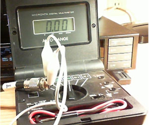
Generally, at this stage, one is only looking for a short that might have occurred during the attachment. Opens are much less likely, although they do occur. A good way to do this is shown in Figure 3. Using alligator clips allows the technician to “wiggle” the cable and connector to further insure there are no intermittent shorts/opens
At some point, it is a good idea to perform an impedance test on the cable. Impedance (Z) is expressed as a combination of Resistance (R) and Reactance (X) and is measured in ohms.
It is expressed as a complex quantity: Z = R + j X. While not particularly difficult to measure, it does require a test setup that responds to AC characteristics. Essentially, it is a test of the characteristic impedance of the cable/connector assembly and should be done with some sort of professional test set.
If both the go/no-go and impedance tests pass, the chances are pretty good that the connector installation was successful. However, even in the best of circumstances, there are a number of subtleties that can occur during the attachment process that will not appear readily obvious but will have an effect on the continuity of the signal.
Any type of incongruency in a cable, or at the cable/connector assembly, will create an impedance mismatch and will affect the RF signal as it passes. It is impossible to eliminate all of the imperfections that cause such degradation – some of them just come with the RF territory. The trick is to minimize that mismatch with a clean, professional transition that meets specs and doesn’t add anything other than the bounded variances (such as specified insertion loss) that are part of the equation. Anomalies such as cold solder joints, bad crimps and contamination (grease, dirt moisture, etc.) can all affect the integrity of the connection.
Therefore, again, as simple as attaching a connector to the cable may sound, a litany of factors must be considered, before, during and after the connection is made.
What can go wrong
On the outside, it seems that cable/connector junctions shouldn’t be all that difficult. The truth is, that when connectors are improperly installed, the failures, with the exception of obvious component separation, are subtler than many other types of connections. The other part of that equation is that it not only affects the signal integrity, but it also affects the longevity of the installation.
The most common failure, some sort of physical compromise when the connection was made, has been discussed at length so far. The other common failure cause is contamination of the components. Contamination by foreign substances is responsible for most failures down the line. Grease, dirt, oils, rosins, solvents, etc, all can cause deterioration of the connection over time. Environmental extremes, usually heat but cold and moisture as well, are also a cause for cable deterioration. Most cables use polyethylene and polyvinyl chloride as insulators.
These two plastics have relatively low melting points and can start to soften at temperatures as low as 65 degrees C. Also, if the cable/connection is exposed to low heat over long periods of time, the position of the center conductor in relation to the shielding may shift as the hot plastics yield. It is even possible to have a tightly bent cable short at the connector when exposed to direct sunlight.
Finally, the most common cause of connector failure is moisture. Waterlogged cable produces altered electrical characteristics, rendering it anything from totally useless, to displaying odd, or intermittent symptoms.
Most moisture-related failures are due to incursion in the connector-to-cable joint because there is a missing or failed external weather seal. Unless special connectors are used, such as the special purpose connector discussed in the appendix, they are not resistant to moisture. We are all familiar with what moisture can do to any number of components, and connectors are no exception. The cardinal rule is to prevent connectors from getting wet by ensuring proper installation of an external weather seal or a connector designed with built-in weather seal. Of course, there are other contributors to failure. Stress on the connection, even age will eventually cause failure of the various components.
The real cost of failure
At the beginning of this paper is the statement… “it is only as good as its weakest link, and if there isn’t enough time or money to do it right the first time, there is always enough time to do it over.” This statement emphasizes how important it is to use quality components, and have the “how to” knowledge to do it right the first time.. Cutting corners, using substandard components, relegating “it’s only a connector” to the experienced tech or simply doing sloppy connector work will always come back to haunt the technician.
Connectors are an extremely critical component in any system. When they fail, so much more goes down with them. The cost of connector failure can have a ripple effect all the way from the top down.
That puts a lot of pressure on what some consider a relatively insignificant component. But if it fails, the significance moves right to the center of the radar screen. Having a connector fail in a mission-critical situation can cause anything from a threat to life-safety to a major loss of revenue.
The bottom line here is that connector failure is, by and large, avoidable. By simply taking this tiny component seriously, taking the time to do the job right, using the right tools and using top-shelf techniques, it can be a one-and-done scenario—every time.
The new normal – Harsh and challenging environments
Coming soon will be a whole new paradigm in wireless networks. With the IoT and 5G looming on the horizon, higher frequencies, smaller components, virtualization and software controlling everything will expand the TX/RX ecosystem like nothing we have seen to date.
Because there will be so many more small networks, the number of connectors will mushroom logarithmically. Security in one form or another—military, remote sensor sites, mm Wave small cells, clouds, heterogeneous networks—all will demand not only the best in connector quality, but also the best in understanding the critical role in connector integrity.
With these new applications, new device technology will be necessary. The tried-and-true 40+- year-old RF connectors that have been the mainstay of the industry for so long are giving way to a new paradigm. Therefore, connectors that extremely linear, environmentally hardy and much more self-installing will be needed to support them. It will require installation to becomes less complex and more automated, freeing the technician’s time and making these new connectors much more reliable, and environmentally bulletproof.
Their strong suit is that they utilize a patented compression technology with unique water-tight capability. These are truly a one-and-done connector. Along with being water tight, they offer a much easier installation with improved system reliability on braided cables.
Due to the easier installation, the chance for bad connections is reduced. They can even be installed by less-experience personnel in a much more automated manner in a shorter amount of time. This will become a very critical metric with the distribution of ubiquitous smart networks, especially in the mm wave spectrum.
There are other advancements as well. Wide-bandwidth, high-density connectors are being refined. New implantable connectors are part of the offering as are specialized lines for wearables. And, let’s not forget backhaul systems, which are expected to see logarithmic growth.
The list goes on and on. But one thing is for sure: The new paradigm is smaller and less reliant on old connection methodologies — and it performs better with faster and easier installation. That is the wave of the future.
Conclusion
Connectors are not necessarily sexy or exciting device. But they are one of the most critical. In the next few years, a new connector evolution will take place. Pressure is on manufacturers to develop small, ultra-wide bandwidth devices that will go from DC to 28 GHz and beyond. And, with an ultra-linear, low-insertion loss requirement. That will require rethinking the current materials, dielectrics and shielding metrics.
The applications for RF connectors will expand by at least an order of magnitude in the next five years. The pressure is on to make RF connectors a plug-and-play components. How that will play out is still a bit foggy. However, one thing is for sure: The old ways will have to give way to the new ways in many cases. RF isn’t going to change. So the fundamental concept of RF connectors isn’t either. There will always be a demand for solid, good connector installation practices, especially on larger cables. But the emerging connector ecosystem will certainly call for some shifts in the RF connector space.
Glossary of terms
- DAS - Distributed Antenna System
- ID – inside diameter
- OD - outside diameter
- VSWR – Voltage Standing Wave Ratio
Appendix A – critical application note
As new types of networks emerge, and mature, such as small cells and intelligent DAS, RF coverage is becoming more ubiquitous. With that, comes the ability to deploy critical life-safety RF systems in locations previously deemed difficult or challenging; specifically, in-building coverage. This gives life-safety a new option. It can now have available full in-building radio coverage
But with that comes a responsibility to make sure the system is bulletproof. It means nothing if a million dollar RF in-building system is deployed and the critical interface, the cables, cannot stand up to the demands. For example, commercial buildings have mandated public safety radio systems. If an automatic fire extinguishing system is deployed due to a fire, it is likely that cables will be in the path of that water at one point or another. It is the designers job to insure that both the cable and the connections are water-tight to insure cable continuity and keep the system on the air so first responders can have reliable communications. This is where ultra-reliable, water-tight connections are demanded, and remove a point of failure.
Similar requirements are demanded for mission-critical infrastructures as well. Natural disasters (floods, earthquakes, storms) can easily cause cable failures if water or other fluids (oils, chemicals) come in contact with the cable. The only guarantee that they will remain intact is to use sealed connectors that prevent ingress of water and other fluids.