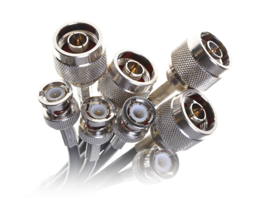
Connections More Vital Than Ever
Today, a flawed coaxial connection can severely reduce performance on digital systems like ThinNET (EtherNET), Wireless networks like WiFi and WLAN’s and high-end video like SDTV, DTV and HDTV. Where just a few years ago a poorly installed CCTV connector might have yielded a 1dB or less loss on a CCTV system, the same bad connection can now yield a 10dB loss on a > 1GHz system. That could mean that only about a third of the signal would get through the connection.
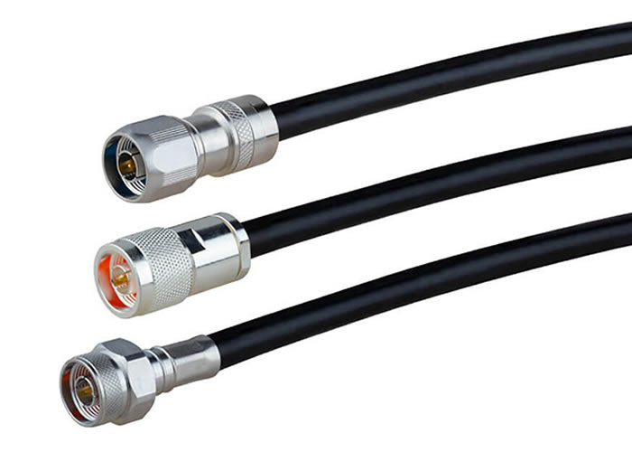
Let’s review a few of the factors to be considered when building coaxial connections and cable assemblies.
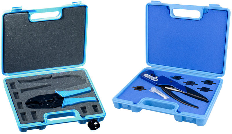
First of all, whether using solder or crimp as your attachment method, you must bring the right tools and skills to the table.
Good tools are not optional. The proper instruments and components, along with the knowledge gained from training and experience, set the stage for success in field and bench installations.
Installing the connector’s center contact to the cable’s center conductor is reliably achieved using either solder or crimp methods. Push-on, twist-on or wire-wrap methods can be very problematical and should not be considered for any assembly needed to perform over 1 GHz.
Both crimp and solder types of connection, properly executed, produce solid mechanical and electrical connections. Some technicians prefer a combination of the two contact installation methods where an assembly will be used in rough conditions or when assembling test probes. The contact connection is first carefully crimped and then solder is flowed into it. Although a technique that can be difficult to master, it creates a connection that will never fail except under conditions of extreme mechanical damage or heat. Never crimp a soldered joint! Solder has no compression strength.
First Step is Cable Prep
Whichever method is used, the cable must first be carefully prepared and stripped according to installation instructions for the connector.
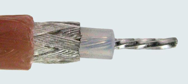
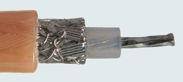
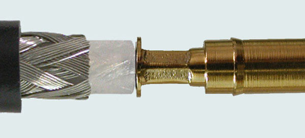
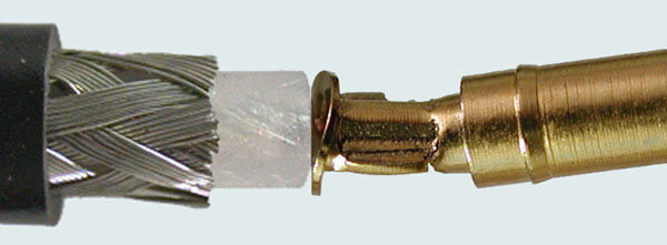
- Preferred result of proper cable prep
- Jacket, braid and dielectric should be stripped at 90 degrees.
- Materials cannot be damaged or distorted.
- Diameter of braid should be less than diameter of the cable jacket.
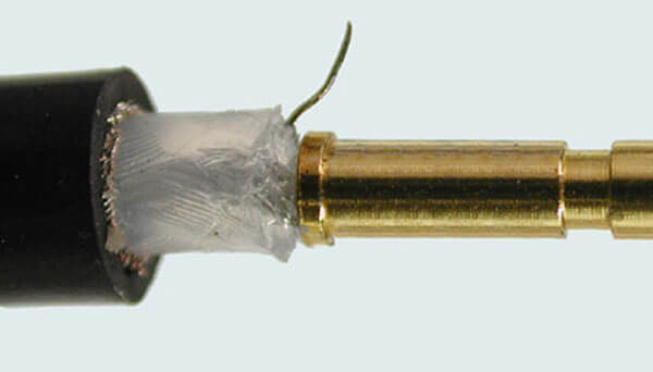
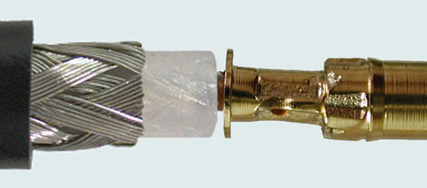
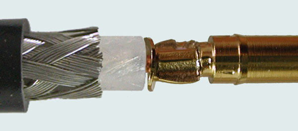
- Nonconforming Cable Prep
- Braid strands must be completely and cleanly stripped to prevent shorting.
- Nonconforming Cable Prep
- Any flare on center conductor and braid is acceptable only if it can be twisted back into position prior to assembly.
Solder
This fabrication method is often considered the most labor-intensive because the connector’s center contact is soldered to the cable’s inner conductor. Performed properly, it is also one of the most reliable connections and can be used on cable with solid or stranded center conductors. If metals and plating of contacts and cable center conductors are compatible and solder-able, and, if the technician is skilled in this type of installation, solder connections can be expected to perform for long periods of use.
Advantages of Solder
Tooling for this method is simple: the main tool is a low-wattage solder iron with an assortment of tips. Installation is aided by the use of a decent vise to hold the work in place while applying solder. Beyond that, the materials consumed are solder and flux.
Soldering is much more tolerant of non-optimum technique.
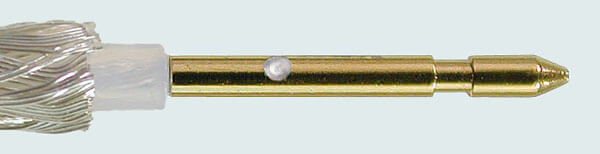
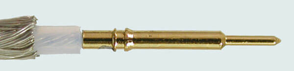
- Preferred Result After Soldering Flexible Braided Coax
- Solder around joint is smooth and shiny
- No evidence of solder flow outside joint region
- Solder hole is filled flush with outside pin/contact surface
- Proper Semi-rigid Coax Techniques Should Show
- Solder around joint is smooth and shiny
- No evidence of solder flow outside joint region
- Preferred Flexible Braided Coax Techniques Should Show
- Dielectric shows clean 90 degree stripping
- No evidence of melting
Disadvantages of Solder
It takes more time to terminate than other methods.
“Cold” solder joints can cause problems if the connector is contact is not soldered properly to the cable, observing solder flow through the contact solder hole.
Soldered joints between the contact and the cable’s center conductor can work harden if subjected to excessive vibration during use and develop micro-cracks followed by solder fatigue.
Soldering can be inconsistent and subject to failure as a result of mechanical or temperature stresses.
Care must be taken to control heat applied during the soldering process and not allow solder to wick or hot tip to distort the cable dielectric.
Results of poor technique are likely to reduce performance. This operation should be corrected or begun anew before continuing with installation.
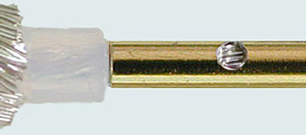
- Nonconforming Solder Results May Show
- Visible braid indicates solder fill less than 75% minimum
- Cavity changes contour of pin
- Electricals will be affected
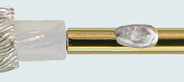
- Nonconforming Result
- Excess solder flow onto body of pin
- Excess solder changes contour of pin
- Electricals will be affected
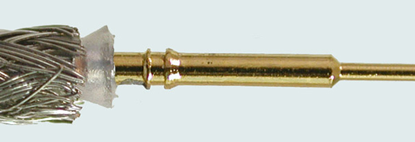
- Nonconforming Result
- Dielectric melted past OD + 20% maximum
- Flare of dielectric will interfere with assembly
- Pin has melted into dielectric
- Pin will not meet interface
Crimp-on
This fabrication method has always been the workhorse of the industry, and is probably the most frequently used method of terminating coax cable with connectors.
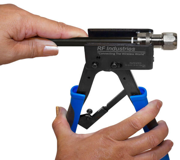
When crimping connector contacts and ferrules, careful selection of proper tools is critical. It is an investment of time and money, which increases productivity while decreasing effort. Use a ratchet crimp tool like the RFA-4005-20; or, if you anticipate thousands of crimps over the tool’s anticipated use, invest in a heavy duty, piston driven crimp handle such as the RFA-4009-20. Select the correct crimping die for your cable, connector and crimp handle. Coaxial crimpers are designed to place the pressure of the crimp evenly around the connector.
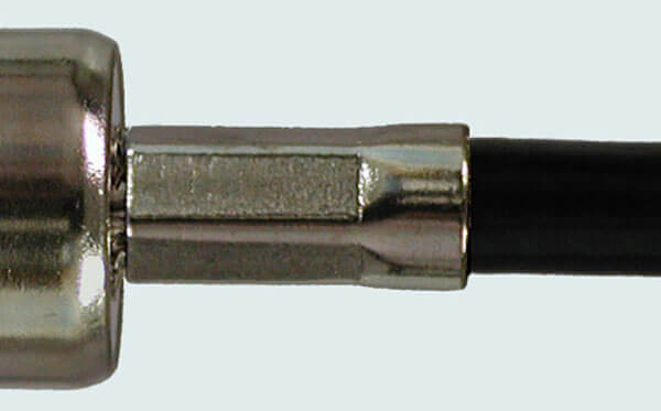
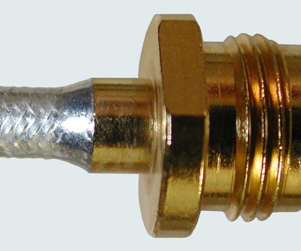
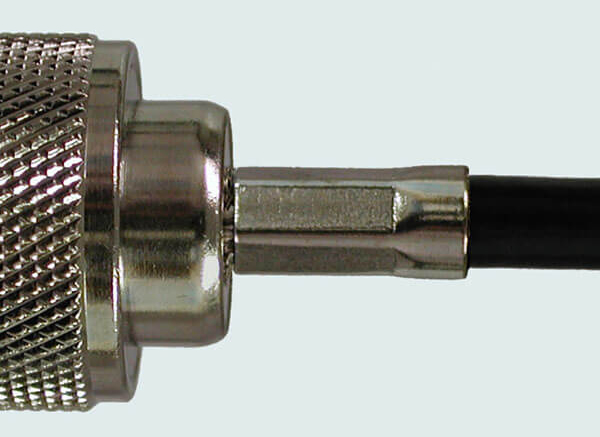
- Preferred Crimp Result
- A properly crimped ferrule will be slightly flared at the mouth. This is called the bell-mouth condition and helps relieve stress on the coax.
Advantages of Crimp-on
There is no need for soldering; therefore, installation time is reduced.
It takes an experienced technician about 15 seconds to install a crimp-crimp connector, thereby greatly reducing the time required to create cable assemblies. This is very important in today’s cabling market where time is of the essence and fewer technicians are being asked to maintain more and more equipment. Digital video, computer and network cabling is almost universally crimped today. If you are precutting for very large commercial jobs, substantial savings can be gained by having your supplier prepare your cables in advance.
Crimped connections, done correctly, can be superior to soldered connections.
A good crimped connection deforms the metal sufficiently past the yield point, but not too much, so that the “spring back” keeps the connection secure, even under thermal cycling (the coefficient of expansion of the two metals might be different) and vibration.
A good crimp connection is gas tight and won’t wick: it is sometimes referred to as a “cold weld”.
Like the solder method, it can be used on solid or stranded conductors, and provides a good mechanical and electrical connection.
- Preferred crimp result
- Equal compression on all 6 crimp surfaces
- Center contact crimp die positioned within pin step down
Disadvantages of Crimp-on
If done poorly, the crimped contact will not seat properly within the connector taking the interface out of specification. Both signal continuity and quality will suffer.
Crimped contacts cannot be un-crimped and re-installed. In many cases, this means the entire connector assembly must be scrapped and replaced by a new one.
Unless crimped with the proper dies using professional crimp handles, crimped connections on solid wire can be poor and prone to failure.
Sometimes, although rarely and under conditions of frequent flex, stranded wire can shift within the crimped joint and loosen. This occurs more frequently with clamp connectors than connectors with crimped ferrule studs.
- Nonconforming Crimp Result
- Position of crimp die is outside crimp area
- Body of pin is no longer concentric
- Impedance of connector will be adversely affected
- Nonconforming Crimp Result
- Pin/Contact has been distorted, is no longer straight or concentric with cable
- Pin/Contact has begun to break at crimp Pin shows “dog ear” of excess material
- Possible cause: wrong crimp die or too much pressure applied
An important point to remember when using the crimp method is to select the proper connector for the coax cable you are using. A tight fit on the inner conductor before the crimp is necessary. The proper ratios of ferrule stud ID to cable dielectric OD and ferrule stud OD to ferrule ID is important to avoid a substandard crimp even with proper tools. Always avoid double crimping, especially on the contact; this is known as “flagging” or “dog ears”.
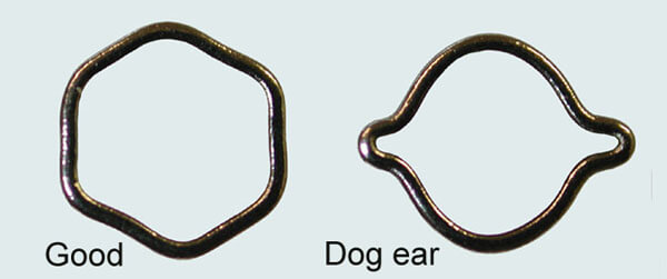
- Ferrule Cross Section
- Reject “dog ear” caused by unequal pressure and excess material that forms “ears”. It is less problem on ferrule than contact but far better to avoid with proper tools and technique.
- Possible cause of “dog ear” is using the wrong crimp die, too much pressure applied, using an incorrect ferrule or the ferrule material may be too hard.
- Correct Ferrule Crimp Result
- Good ferrule crimps create a hexagon shape with equal pressure on all sides
- Crimp die positioned at front of ferrule, near connector
- Equal pressure from crimp die on all sides
- “Bell” at rear of ferrule allows cable flexibility
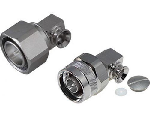
Compression
Although relatively new to wireless communications, compression connector attachment was developed and predominantly used by the cable TV industry. As with crimp or solder connector attachment, there are pros and cons to compression connector attachment.
Advantages of Compression
- Simple and fast field installation using hand tools with little experience needed
- Superior pull strength compared to crimp or solder
- Superior weather seal
- Piece connector with no components to lose or improperly install
Disadvantages of Compression
- Specialized tooling required for cable preparation and connector attachment
- Limited connector to cable selections
- Higher connector cost compared to crimp or solder
Connector Attachment and Low PIM
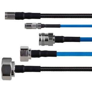 Passive Intermodulation (PIM) is essentially interference caused by unwanted signals mixing in the passive components of a wireless network. Some wireless networks like LTE are more susceptible to PIM. Installing low PIM components can avoid this problem. There are three elements to cable assemblies for low PIM performance. The connector and cable must be designed and manufactured to exhibit low PIM performance. Most braided cables will not qualify as low PIM. The connector to cable connection is the third important element in low PIM performance. The ground connection must be robust, uniform and consistent. Although crimp connectors provide adequate electrical and mechanical performance they generally exhibit poor PIM performance. Specially designed solder connectors will perform well at reducing PIM. To achieve good grounding, specialty soldering methods and tools are required. High power inductive soldering stations apply concentrated heat to effectively melt and flow the solder without damaging the cable or connector. Due to the large size and power requirements of induction solder equipment; attachment of low PIM solder on connectors in the field is not an option. Specially designed compression connectors and installation tools for corrugated cables may be used for field installation with good low PIM results.